


Spin a Stepper Motor with an ESP32 and a DRV8825
This is the quickest path I know to get a stepper motor moving with an ESP32. No libraries and no fancy acceleration. Just one small sketch that turns the motor one way, rests, turns it back, and rests again.
If you’ve made an LED blink on an Arduino, you already know almost everything you need. A stepper driver is basically an LED you blink really fast.
What it does
- Turns the motor clockwise for 1 second (one full revolution)
- Rests for 9 seconds with the motor powered off
- Turns it counter-clockwise for 1 second
- Rests for 9 seconds
- Repeats forever
What you need
- ESP32 dev board (I used an HW-394, a common 30-pin ESP32-WROOM-32 board)
- DRV8825 stepper driver board (the small purple Pololu-style one)
- A bipolar stepper motor with 4 wires (a typical NEMA 17)
- A motor power supply between 8.2 V and 45 V (12 V is a good choice)
- A 100 µF electrolytic capacitor (anything from 47 µF up works), rated above your supply voltage
- Jumper wires and a breadboard
- VS Code with PlatformIO (the Arduino IDE works too)
How it works, in plain English
A stepper motor doesn’t spin freely like a normal DC motor. It moves in small, exact clicks called steps. A common stepper has 200 steps per revolution, so each step is 1.8°.
Making those steps happen means switching fairly large currents through the motor’s two coils in exactly the right order. Your ESP32 can’t do that on its own, and that’s the job of the DRV8825. It handles the heavy lifting and the coil switching. All it needs from you is two signals:
- STEP: each time this pin goes from LOW to HIGH, the motor moves one step.
- DIR: HIGH turns the motor one way and LOW turns it the other.
That’s the whole interface. To spin the motor, you set DIR and then pulse STEP over and over, like blinking an LED. The faster you blink, the faster the motor turns.
The DRV8825 also has a SLEEP pin. Pull it LOW and the driver turns the motor completely off, so no current flows and nothing gets warm. Pull it HIGH and the driver wakes up, ready to step.
Wiring
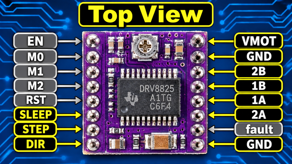
Gray pins are not required. Yellow pins are required.
| DRV8825 pin | Connect to | Why |
|---|---|---|
| STEP | ESP32 GPIO32 | One pulse = one step |
| DIR | ESP32 GPIO33 | Sets the direction |
| SLEEP | ESP32 GPIO25 | LOW = motor off, HIGH = awake |
| RESET | ESP32 3.3 V | Must be HIGH or the driver does nothing |
| ENABLE | Leave unconnected | It defaults to enabled |
| M0, M1, M2 | Leave unconnected (or GND) | All LOW = full-step mode |
| GND (logic, next to FAULT) | ESP32 GND | The ESP32 and driver must share a ground |
| VMOT | Motor supply + | Powers the motor |
| GND (next to VMOT) | Motor supply − | |
| A1, A2 | One motor coil | |
| B1, B2 | The other motor coil |
Don’t skip these:
- Put the capacitor across VMOT and GND, as close to the driver as you can, with the stripe (−) side to GND. Without it, voltage spikes can kill a DRV8825.
- Never plug or unplug the motor while the driver is powered. That can kill it too.
- Finding the coil pairs: with the motor disconnected, check the wires with a multimeter on its resistance setting. Two wires that read a few ohms between them are one coil. Two wires from different coils read “open”. Most NEMA 17 motors with 4 wires use the order A1, A2, B1, B2 on the connector, but check yours.
Set the current limit (5 minutes, worth it)
The little screw on top of the DRV8825 is a potentiometer that sets how much current the driver sends to the motor. Too high and the driver and motor overheat. Too low and the motor is weak or skips steps.
- Find your motor’s rated current per phase on its datasheet (for example, 1.0 A).
- Power the driver with the motor supply. The motor can stay disconnected for this.
- Measure the voltage between the pot’s metal top and GND. That reading is Vref.
- On Pololu-style boards: current limit = Vref × 2. For a 1.0 A motor, turn the pot until Vref reads 0.5 V.
(If your board is a different design, check its sense resistors. That formula is for the usual 0.1 Ω resistors.)
The PlatformIO setup
Create a new PlatformIO project and pick Espressif ESP32 Dev Module as the board. Your platformio.ini should look like this:
[env:esp32dev]
platform = espressif32
board = esp32dev
framework = arduino
monitor_speed = 115200
Watch out: make sure the board is esp32dev. Variants like the ESP32-C3 don’t have GPIO32 and GPIO33 at all, and the code won’t work.
The code
Paste this into src/main.cpp:
#include <Arduino.h>

constexpr uint8_t PIN_STEP  = 32;
constexpr uint8_t PIN_DIR   = 33;
constexpr uint8_t PIN_SLEEP = 25;   // -> DRV8825 SLEEP (active low)

constexpr uint32_t STEPS_PER_REV = 200;   // 1.8 deg motor, full step
constexpr uint32_t RPM           = 60;
constexpr uint32_t MOVE_MS       = 1000;
constexpr uint32_t PAUSE_MS      = 9000;

constexpr uint32_t STEPS_PER_SEC  = STEPS_PER_REV * RPM / 60;         // 200
constexpr uint32_t STEP_PERIOD_US = 1000000UL / STEPS_PER_SEC;        // 5000 us
constexpr uint32_t STEPS_PER_MOVE = STEPS_PER_SEC * MOVE_MS / 1000;   // 200
constexpr uint32_t PULSE_HIGH_US  = 10;   // DRV8825 needs >= 1.9 us
constexpr uint32_t WAKE_US        = 2000; // DRV8825 needs 1.7 ms after wake
constexpr uint32_t SETTLE_MS      = 50;   // let rotor stop

void driverWake() {
  digitalWrite(PIN_SLEEP, HIGH);
  delayMicroseconds(WAKE_US);
}

void driverSleep() {
  delay(SETTLE_MS);
  digitalWrite(PIN_SLEEP, LOW);
}

void move(bool clockwise) {
  digitalWrite(PIN_DIR, clockwise ? HIGH : LOW);
  driverWake();

  uint32_t next = micros();
  for (uint32_t i = 0; i < STEPS_PER_MOVE; i++) {
    digitalWrite(PIN_STEP, HIGH);
    delayMicroseconds(PULSE_HIGH_US);
    digitalWrite(PIN_STEP, LOW);

    next += STEP_PERIOD_US;
    while ((int32_t)(micros() - next) < 0) { }
  }

  driverSleep();
}

void setup() {
  pinMode(PIN_SLEEP, OUTPUT);
  digitalWrite(PIN_SLEEP, LOW);

  pinMode(PIN_STEP, OUTPUT);
  pinMode(PIN_DIR, OUTPUT);
  digitalWrite(PIN_STEP, LOW);
  digitalWrite(PIN_DIR, LOW);

  Serial.begin(115200);
  delay(500);
  Serial.println("DRV8825 test starting");
}

void loop() {
  Serial.println("CW");
  move(true);
  delay(PAUSE_MS);

  Serial.println("CCW");
  move(false);
  delay(PAUSE_MS);
}
Click Upload (the → arrow in the PlatformIO toolbar), then open the Serial Monitor (the plug icon). You should see “CW” and “CCW” printed while the motor turns.
Walking through the code
1. Pin numbers
constexpr uint8_t PIN_STEP  = 32;
constexpr uint8_t PIN_DIR   = 33;
constexpr uint8_t PIN_SLEEP = 25;
This is the same as int ledPin = 13; in Blink. constexpr just means “this value never changes”, and uint8_t is a small whole number. If you want different pins, change them here.
2. The numbers that set the speed
constexpr uint32_t STEPS_PER_REV = 200;
constexpr uint32_t RPM           = 60;
These are the only values you need to touch to change the speed. The code works out the rest:
- 60 RPM is 1 revolution per second.
- 1 revolution is 200 steps, so we need 200 steps per second.
- 1 second ÷ 200 = 5 milliseconds between steps (5000 microseconds).
- The move lasts 1 second, so that’s 200 steps per move, exactly one full turn.
uint32_t is just a bigger whole number, big enough to hold microseconds.
3. Making one step: Blink, but tiny
digitalWrite(PIN_STEP, HIGH);
delayMicroseconds(PULSE_HIGH_US);
digitalWrite(PIN_STEP, LOW);
This is the heart of the whole project, and it’s Blink. Pin HIGH, short wait, pin LOW. The only difference is that the wait is 10 microseconds instead of 1000 milliseconds. The DRV8825 only needs the pulse to last about 2 microseconds, so 10 is plenty.
Each time the pin goes HIGH, the motor clicks forward one step.
4. Keeping a steady beat
next += STEP_PERIOD_US;
while ((int32_t)(micros() - next) < 0) { }
You could just write delayMicroseconds(5000) here and it would mostly work. The problem is that the other lines in the loop take a little time too, so each step would run a bit late and the motor would turn slightly slower than you asked for.
Instead, the code keeps a running “next step is due at” time, adds 5000 µs to it every step, and waits until micros() (the ESP32’s microsecond stopwatch) catches up. That keeps the beat exactly on time, much like a metronome. The odd-looking (int32_t) cast keeps the comparison correct even when the stopwatch rolls over back to zero, which happens about every 71 minutes.
5. Direction
digitalWrite(PIN_DIR, clockwise ? HIGH : LOW);That’s shorthand for “if clockwise, write HIGH, otherwise write LOW”. Set DIR first, then pulse STEP. If your motor turns the wrong way, swap HIGH and LOW here, or swap the two wires of one coil.
6. Sleep and wake
void driverWake() {
  digitalWrite(PIN_SLEEP, HIGH);
  delayMicroseconds(WAKE_US);
}
The DRV8825 needs about 1.7 milliseconds to wake up before it listens to step pulses. We give it 2 ms to be safe.
void driverSleep() {
  delay(SETTLE_MS);
  digitalWrite(PIN_SLEEP, LOW);
}
After the last step, we wait 50 ms for the motor to come to a complete stop, then pull SLEEP LOW. From then on, no current flows through the motor coils.
Why bother? A powered stepper that isn’t moving still pulls its full current to hold its position, and it gets warm doing nothing. If your project only moves now and then, sleeping between moves saves nearly all of that power.
The catch: while it’s asleep, the motor has no holding torque. If something pushes or hangs on the shaft, the shaft can turn. For a light load that’s fine. For a heavy or spring-loaded one, plan for it.
7. setup()
pinMode(PIN_SLEEP, OUTPUT);
digitalWrite(PIN_SLEEP, LOW);
The first thing we do after power-up is put the driver to sleep, so the motor stays off until we actually want to move it. Then the STEP and DIR pins become outputs, the same as pinMode(ledPin, OUTPUT) in Blink.
8. loop()
move(true);        // clockwise
delay(PAUSE_MS);   // rest
move(false);       // counter-clockwise
delay(PAUSE_MS);   // rest
It reads like the description at the top of this post. move() wakes the driver, takes 200 steps and puts the driver back to sleep. delay() is the same delay you used in Blink.
Changing it
| I want to… | Change this |
|---|---|
| Go faster or slower | RPM |
| Move longer or shorter | MOVE_MS |
| Rest longer or shorter | PAUSE_MS |
| Use a 0.9° (400 step) motor | STEPS_PER_REV = 400 |
Steppers lose torque as they speed up, and without gradual acceleration they can stall if you start them too fast. If the motor just buzzes at a higher RPM, back the speed off.
Troubleshooting
- Nothing happens at all: check that RESET is wired to 3.3 V, that SLEEP is wired to GPIO25, that the motor supply is on, and that the ESP32 GND is connected to the driver GND.
- The motor buzzes or shakes but doesn’t turn: the coil pairs are probably mixed up. Find them again with a multimeter. A current limit that’s too low can also do this.
- It turns the wrong way: swap HIGH and LOW in the DIR line.
- The driver gets very hot: turn down the current limit.
- The upload fails with pin errors, or the motor does nothing at all: make sure
board = esp32devinplatformio.ini.
Where to go next
Once this works, the natural next step is a library like AccelStepper or FastAccelStepper. These ramp the speed up and down smoothly so you can run much faster without stalling. Under the hood they’re doing the same thing you just wrote: setting DIR and pulsing STEP.